|
Making a Use Case Diagram
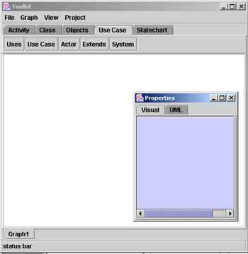
Open the toolkit as explained earlier and select the
Use Case tab. Your window should look like this:
Use cases are textual descriptions of the interaction
between external actors and a system. An use case will have an actor, a
system, an use case and the interface. The tool kit
has a tool bar which features all the elements that can be used to make a
use case diagram.
Working with Elements of the Use Case Diagram
Click on each tab in the tool bar to see all the symbols
that the tool kit supports.
First click on the use case tab and then click on
the white screen, You will notice an use case element on the screen.
Similarly, try clicking all the element on the tool bar
and put them on the screen. Your screen should
look like this:
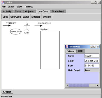
Notice:
-
The properties applet changes for every element,
showing mainly the color, dimensions, HTML link and Graph link. The
use case and the system elements have more properties
such as the name and border size.
-
The properties can be changed by changing the text in
the respective text areas. Notice the changes appearing on the screen.
Changing the Size of the Elements
Click on the element, you will notice small green boxes on
the edges of the selected element. Click on those boxes and
simultaneously drag the mouse to adjust its size according to your use.
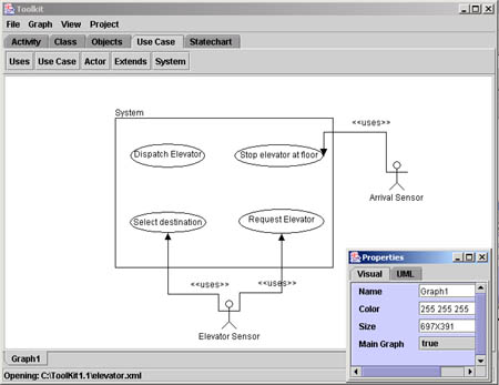
Elevator Example
Let us take the example of an Elevator system to learn
how to make a use case of any system using the toolkit.
Actors: Elevator user, Arrival sensor
As the elevators moves between floors, the arrival sensor
detects that the elevator is approaching a floor and notifies the system.
The system also determines in which direction the system should move in order
to service the request of the elevator user.
-
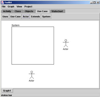
Select the actor icon on the tool bar and then place
the actor on the screen. Since we have two actors repeat the process
for the second actor.
-
Now click on the system icon and the click the screen
to make the system boundary.
Your screen should look like this, If not then select the actor or the
system on the screen and move it to place them in the positions shown
below::
-
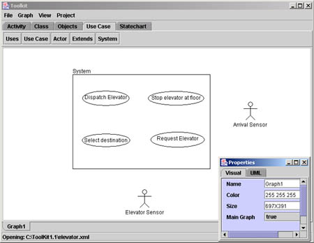
Adjust the system boundary size by selecting it and
then click any of the green box to change the size. Change the name of
the system using the property applet to 'elevator' and notice the
change on the screen when you press enter.
-
Similarly change the names of the actors using the
property applet that appears when each actor is selected.

-
Now select the use case icon and click the screen
where you want to place the use case.
-
Change the name of the use case using the respective
property applet of each use case.
-
Now we have to connect the actors to the use case.
Select the 'Uses' icon on the tool bar and then click the mouse next
to the actor. You will see an arrow drawn.
-
Now click on the yellow box and drag it to point it to
the use case. Similarly select the green box and drag it to the actor.
-
Now connect the use cases to each other as shown below
using the Extend icon on the tool bar.

|