Diagrams
|
|
How to make Activity Diagram?
Open the toolkit as explained earlier and select the Activity tab.
Your window should look like this:
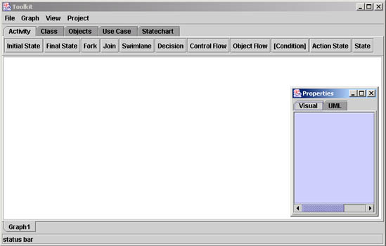
Activity diagrams provide a visual reference for
documenting sequences of tasks making up a single activity. The tool kit
has a tool bar which features all the elements that can be used to make an
activity diagram.
How to work with elements, used to represent the activity
diagram of a system?
Click on each tab in the tool bar to see all the symbols that the tool kit
supports.
First click on the use case tab and then click on
the white screen, You will notice an use case element on the screen. Similarly
try clicking all the element on the tool bar and put them on the screen.
Your screen should look like this:
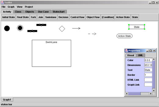
Notice:
-
The properties applet changes for every element, showing mainly
the color, dimensions, HTML link and Graph link.
The 'State' and 'Action State' elements have more properties
such as the name and border size.
-
The properties can be changed by changing the text in
the respective text areas. Notice the changes appearing on the screen.
How to change the size of the elements directly on the
screen using the mouse?
Click on the element, you will notice small green boxes on
the edges of the selected element. Click on those boxes and
simultaneously drag the mouse to adjust its size according to your use.
Example
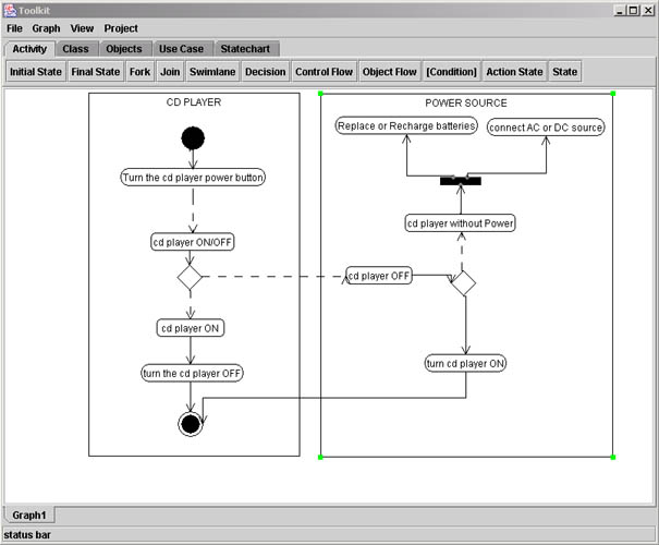
Let us take the example of a CD Player to learn how to make a
use case of any system using the toolkit.
-
Primary Actor(s) : Music Fan!, External Power Source.
Description : The Music Fan turns the CD player On (or off).
Preconditions : The CD player is turned off (or on)
Flow of Events : The music fan! presses a switch to turn the CD
player on (or off):
- If the CD player is off, pressing the switch will turn the CD
player off.
- If the CD player is on, pressing the switch will turn the CD
player off.
Post conditions : The CD player is turned on (or off)
Alternative Flow of Events : An adequate CD player power source
may be unavailable:
- Flat (regular) batteries should be replaced.
- Rechargeable batteries should be recharged.
- Or, connect CD player to AC/DC power source.
Assumptions : Battery and AC/DC power sources are available.
-
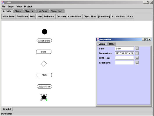
Select the initial state icon on the tool bar and then
click on the screen. Similarly select the final state icon and place
it on the screen.
-
Now click on the action state icon and the click the screen
to place it at the place you want to according to your activity
diagram. Repeat the same procedure for the second action state.
-
Select the decision icon from the tool bar and place
it on the screen.
-
Now select the state element from the tool bar
and place it on the screen twice.
Your screen should look like this, If not then select each the element
and move it to place them in the positions shown below::
-
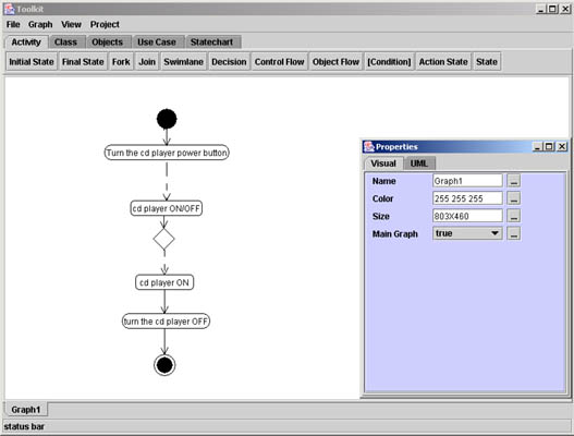
Change the name of the elements using the properties applet and notice the
change on the screen when you press 'enter' key.
-
Use the control flow and the action flow to connect
the different states. Click on the each icon tab and then click on the
screen. Select the arrow and drag it to the corresponding elements.
-
Now select the swim lane icon and click the screen where you want
to place the swim lane
-
Change the name of the swim lane using the respective property applet.

-
We have assumed that the battery or AC/DC power is available,
so now let us connect the above made activity diagram with
with the source of power.
-
Continue working with the same screen. And place three
action state and two states on the screen according to your model.
Also place the decision box in the center as seen below.
-
Connect all the elements with control flows and action flows.

-
Using the Property applet change the names of the states according
to your model and then make a swim lane as described earlier.
|