WelcomeWelcome to the home page of Team LASER. We are the premiere design team in the Clark School of Engineering. Please feel free to explore our website and ask any questions (simply send us an email) about our project. |
WelcomeWelcome to the home page of Team LASER. We are the premiere design team in the Clark School of Engineering. Please feel free to explore our website and ask any questions (simply send us an email) about our project. |
A dental clinic environment has been set up in the Advanced Design and Manufacturing Laboratory (ADML). Under such an environment high speed machining has been carried out to remove dental ceramic material to simulate a process in which dental restorations are being fabricated. However, new machining technologies are needed for the material removal process.
Machining operations, such as turning, milling, grinding, and others are widely used in industry. Machining is a manufacturing process in which a cutting tool is used to remove excess material from a part in order to obtain the desired part shape. One of the new processes of machining is the use of a laser. The laser is a device which uses natural oscillation of atoms or molecules between energy levels to generate coherent electromagnetic radiation (light). This radiation is focused and amplified in the laser by a series of mirrors or waveguides. The light emmitted from the laser possesses tremendous amounts of energy and intensity which can be used for a variety of applications. The use of lasers in machining applications is growing. In our project a Carbon Dioxide laser is to be tested for use in the machining of dental materials.
Our specific goals and objectives to further address the factors related to the laser machining process are:
The present laser positioning system (used in the ADML Lab) is a rigid design that does not allow easy movement of the laser in the vertical or horizntal directions. Our team's objective was to improve upon this design. Upon researching several optical positioning systems produced by several industry leaders, we decided to benchmark the concept of a laboratory jack. Most laboratory jacks are designed to provide smooth, stable height adjustment and high load capacity. The jacks usually operate by a drive screw that changes the distance between pivot pins which lowers or raises an attached plate. However, most of these jacks are designed for generic lab equipment use. Team LASER improved upon the design by customizing the top plate to securely hold the Carbon Dioxide Laser used in the machining process. In addition, the drive screw mechanism is modified to allow for very fine-precision control (in the vertical direction) of the laser system. The design is lightweight and can be easily assembled and disassembled. In addition, the design of a special vise fixture to secure the ceramic specimens during the laser aided hot machining process is performed. The design is optimized to reduce the amount of heat dissipated from the specimen. Thereby, reducing the likelihood of thermal fracture.
CAD Modeling using PRO/EngineerOptical Jack The entire conceptual design of the laboratory jack was created in the PRO/Engineer environment. An actual three dimensional geoemetry can be seen below. PRO/Engineer allowed us to easily visualize how our design would work and how the actual dimensions of the various parts would interact. Also, using PRO/Engineer helped us to save a significant amount of time when design changes had to be made.
|
|
Figure 1. Optical Jack |
|
|
|
|
ViseA special fixture used to constrain ceramic specimens during laser aided hot machining processes. The design is optimized to reduce the amount of heat dissipated from the specimen. Thereby reducing the likelihood of thermal fracrure. The following is a diagram of the fixture using Pro/ENGINEER. |
|
Figure 2. Vise fixture |
|
|
|
|
| Hardness Tester The hardness tester is used in the laser aided machining process to better understand the malleability of the ceramic specimen as a result of the heating from the laser. |
|
Figure 3. Hardness tester |
A laser safety screen was designed and fabricated to prevent personal injury and property damage due to scattering of laser radiation. The design is self standing with a protective high temperature coating.
| In the laser machining tests that are being done in the ADML lab,
the laser will be focused onto the ceramic specimen surface. The energy from the laser
will heat up the specimen in such a manner that the material will become maleable. This
state is ideal for machining the specimen. However, our team wanted to investigate if
there was an ideal area on the ceramic specimen on which to focus the laser that would
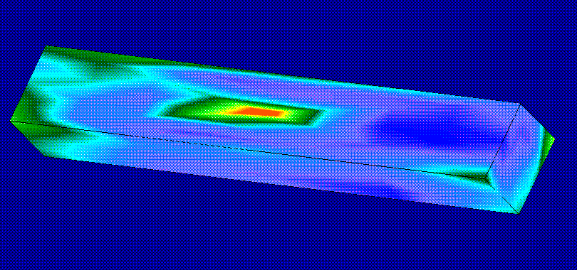
optimize the workability of the specimen. PRO/Mechanica, an FEA tool compatible with PRO/Engineer, is used to perform a thermal finite element analysis of the specimen. Global thermal loads and a heat sink load are applied to the specimens and an analysis is performed. A solid model of the stresses and deformation of the specimen can be seen to the right. |
 |
Figure 4. Temperature distribution of specimen |
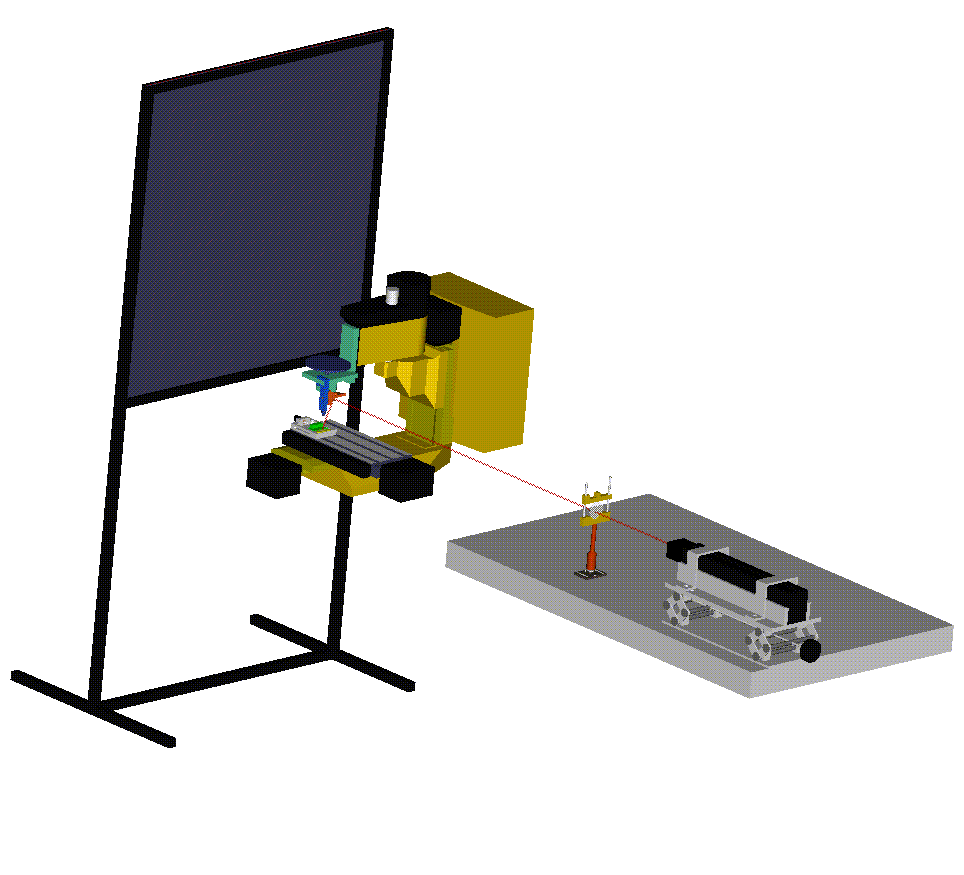
| A representation of the entire laser aided machining setup can be seen here complete with all parts designed using Pro/ENGINEER. |  |
Figure 5. Final assembly |