ENME 414 Computer Aided Design
Team 1
Spring 1998
The project of developing a mouth motion simulator has been carried out for the last two semesters. The objective of this project is to develop a combined mechanical and electrical system capable of simulating the chewing motion of a human mouth. Two student teams made many contributions in the development. The third development(which is our brainchild) stage mainly focuses on two critical issues:
Spring 1998 Final Design
With the intent of creating a better mouth motion simulator, Team 1 redesigned and manufactured the MMS by reducing the number of teeth, reducing a translation direction, adding a radial motion, relocating the Z-direction load cell and upgrading the data acquisition system.
Past Design Summary
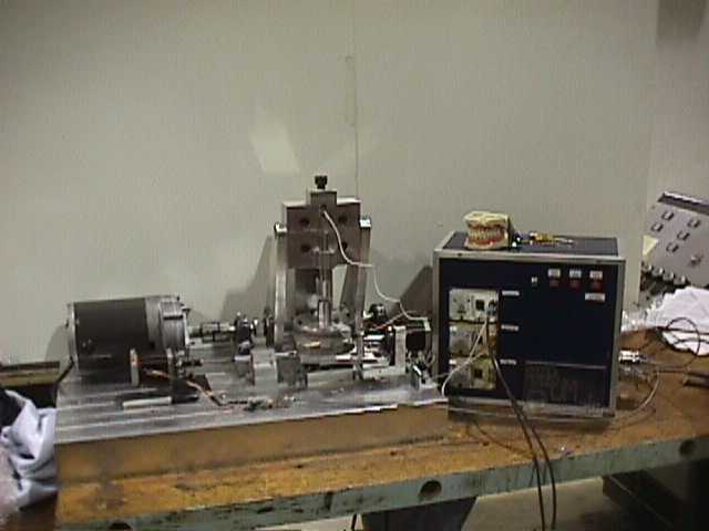
Last semesters Mouth Motion Simulator (MMS), was comprised of subsystems that worked in tandem to simulate a chewing motion in three directions for a pair of upper and lower teeth.
A DC motor, rotating at 120 RPM, drives the vertical or Z-direction mouth motion by articulating two arms that push and pull the upper teeth holder that rides along a vertical table. The movement is transmitted along a shaft from the electric motor to a cam system on each arm with an eccentricity that causes the vertical subassembly to oscillate.
The vertical subassembly house a pair of springs that force the upper tooth holders to their bottom most position until contact is made between the vertically stationary bottom teeth and the mobile upper teeth. An electronic relay determines the position of the subassembly to synchronize the motion in all three directions. The in the vertical direction is measured by a piezoelectric cell below the plate that holds the lower set of teeth.
A pair of linear translation tables held together by springs and pushed apart by a computer controlled stepper motor creates the motion in the X-direction. The displacement in the Y-direction is produced in the same fashion. These subsystems are attached perpendicularly and have individual load cells to measure the loads in the X-Y directions on the lower pair of teeth.
A data acquisition program was written in LabView for collecting data from the load cells. There is a signal conditioning circuit that links up the load cells to the computer where acquired data is monitored and analyzed. When the machine is turned on, the control program begins by executing an initialization process to set the home position of each stepper motor (X and Y axis). The Z motor is later turned on, beginning with the vertical oscillation, and a pulse from the timing sensors triggers a run sequence. At that point, the stepper motors begin actuating the horizontal displacement.
As the vertical and horizontal displacement occurs, simulating human mastication, the chewing forces are measured by the load cells. The last group was not able to successfully transmit data from the load cells to the PC. Furthermore, Each load cell has a conversion factor of approximately 51 mV/Ibf.
There were problems..................
The most current design of The Mouth Motion Simulator, prepared by the Fall 1997 ENME 414 students, was a major step towards the development of an actual mechanical device that simulates the chewing motion of humans. Unfortunately, the design still has room for improvement and requires a redesign.
One of the most important problems addressed was the misalignment of the X-Y subsystem and vertical motion of the plunger subassembly. Investigation into correcting this problem entailed software enhancement. Another remedy may be to install faster stepper motors to move the X-Y subsystem faster to keep up with the plunger assembly.
The stepper motor load cell coupling created major vibration when the unit was placed in operation. The subassembly required a better means of mounting the load cell. The vibration of the threaded shafts of the stepper motors were also a concern and a means of supporting this rod either by a flanged support or a grooved fillet surface was needed.
Even though the teeth that were used in the model replicate human teeth, they do not align in the same manner as the maxillary and mandibular jaws do during the chewing motion. The mandibular actually rotates slightly when the teeth first meet. The existing system lacks this rotation about the vertical direction and therefore lacks an amount of accuracy.
To deal with the complexity of the X-Y directional translations, a small amount of accuracy will be sacrificed to compress the X-Y subassemblies into one subassembly following an X-Y trajectory. The trajectory is documented to have a curvature but is so slight that it can be approximated to a straight line. This single subassembly will incorporate the fundamental components of one of the original X-Y direction subassmblies and will, in essense, just eliminate one set. Additional benefits to this setup include a trajectory that can have any orientation and a savings in cost of one set of linear tables and a stepper motor.
![]()
The added rotational displacement will be accomplished by a subassembly rotating atop the linear translation plate.