
PLEASE PRINT OUT THESE PAGES FIRST AND THEN KEEP THE PRINTED TEXT BESIDE
YOU AS A GUIDE WHEN YOU LOAD AND RUN "NEURON". THIS WILL SAVE YOU HAVING
TO JUGGLE BETWEEN NEURON AND NETSCAPE WINDOWS ONCE YOU HAVE THE SIMULATION
LOADED.
To begin working with this chapter you should have downloaded and installed
Neuron, as described in Chapter 1.

The various windows and graphs that you see are explained below.
The voltage distribution
will now look like this. Make sure you understand why it has this shape
before you move onto the rest of the Exercise.
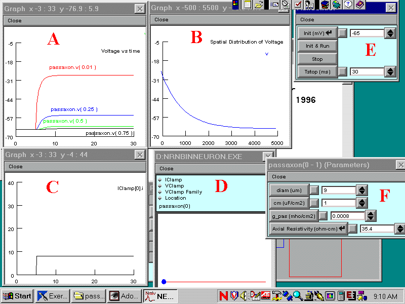
When you have loaded the simulation you should see Windows arranged
as below. Click on the following letters: A B
C D E F
for a description of the function of each Window.
Return to Instructions

A. Graphs of membrane potential (mV) vs time (ms) recorded
by voltage electrodes placed at the various positions along the axon or
dendrite.
Return to letters
B. Graph of the calculated membrane potential (mV) as a function of the distance (mm) along the axon.
Return to letters
C. Graph of the current (nA) passed through the stimulating electrode.
Return to letters
D. Stimulation Parameter Window: As shown, this allows
you to view and alter the position of the current electrode (blue
dot) along the axon or dendrite (red line) click on various places along
the red line to move the stimulating electrode.
Click on "IClamp" to view and alter the stimulating current.
You do not need to bother about the other buttons, which are not relevant to this simulation.
Return to letters
E. The Run/Control Box - click on Init & Run to run a simulation.
Return to letters
F. The parameters of the axon:
diam - the axon or dendrite diameter
cm - the specific membrane capacitance
g_pas - the passive membrane conductance
Axial resisistivity, Ra - the resistivity of the cytoplasm
Return to letters
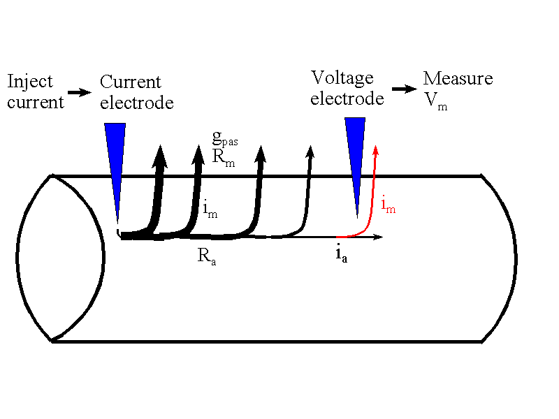
The situation that is being simulated is shown below. The axon or dendrite
is simulated as a cylinder of membrane which contains only passive, voltage
- independent channels - it's much easier to think about this first without
adding any voltage-dependent channels The axon is impaled by two electrodes.
The current electrode is placed at one end of the axon or dendrite and
a voltage electrode can be placed at varying distances along the dendrite
or axon.

The injected current will flow out across the axonal membrane and create
a depolarization of the membrane. However, not all of the current that
is injected into the axon reaches the voltage electrode. As it travels
down the axon some of it (the membrane current, im shown
in black in the figure) leaks out through the membrane before it gets there.
Only the membrane current that is shown in red, traveling across the axonal
membrane close to the site of the voltage electrode, will result in a change
in membrane potential at the site of the voltage electrode. Since this
current (red line) is necessarily less than that which leaks out close
to the current electrode (black lines), the voltage change produced by
the stimulating current diminishes as the voltage electrode is placed
further down the axon, away from the source of the stimulating current.
The rate at which the voltage signal diminishes depends on the ratio
between the axial resistance per cm of axon (ra) and the membrane
resistance of a cm of axon, rm , (the latter in the case of
our simulation being inversely proportional to the passive membrane conductance,
1/gpas). This is because a high membrane resistance and low
axial resistance will tend to keep current flowing down the axon and will
increase the amount of current able to flow out of the membrane at the
site of the voltage electrode.
For a steady, constant current, the exact form of the decline in the amplitude of the steady voltage change with distance from the electrode is exponential:
Vx=Vo.exp(-x/l)
where:
Vo is the voltage change produced by the stimulating current
at the site of the current electrode
Vx is the voltage change produced by the stimulating current
at the site of the voltageelectrode positioned at a distance, x, from the
current electrode
l is
the "space constant" which determines the rate at which V declines with
x. Not surprisingly, l
depends on the membrane and axial resistance and is equal to (rm/ra)1/2
A large membrane resistance therefore results in a large l, which means that stimulating currents can produce large voltage changes over long distances down the axon.
What does all of this mean for the design of axons and dendrites?
As the diameter of an axon increases, axial resistance declines faster than membrane resistance (because axial resistance depends on the axonal cross sectional area - proportional to the square of the diameter - whereas membrane resistance is directly proportional to the diameter). Since l = (rm/ra)1/2 , this means that as axonal or dendritic diameter increases so does l. Therefore:
Voltage changes
spread further by passive propagation down large diameter dendrites
and axons
or put another way:
There is a limit as to how small a dendrite or axon can be made and still allow voltage changes to pass down it efficiently.