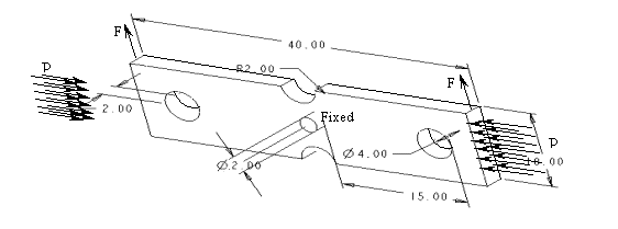
You are asked to use a constraint case including all these constraints.
Analyze the results obtained from a combined use of Pro/ENGINEER
and ANSYS codes. Your work should be as detailed as possible. The
minimum requirement includes the stress distribution along the
longitudinal direction and the deflection in the vertica l direction.
Different mesh methods, such as shell mesh and solid mesh, should be used
to compare their results and gain a better understanding of the accuracy
and computing time. You may evaluate your results from the two solution
methods (Nodal soluti on and element solution available in ANSYS) in your
discussion. This will allow you to distinguish the errors associated with
Pro/ENGINEER from the errors associated with ANSYS.
Since the geometry and the load case both are symmetrical, you should
think about a set of constraints on the central plane to simplify the
solution procedure. This is critical when you use FEA. A common approach
would be to analyze a half of the whole
structure.
For checking your results, you may use the ADML printer. Using a
color printer to demonstrate the stress distributions and deflection is
required. Therefore, ftp your file to homework7 subdirectory of guest
account, keep in mind that you should use y our login name at ADML
computer system for your image file's name to avoid any possibility of
using the same file name. Otherwise, someone's file could be replaced by
others.