Four Point Bending Redesign
Four Point Bending Redesign
 [Claudius Jorif][Jeff Cox][Chetan Sayal][Casey O'Connor]

Abstract
Our mission is to improve the original four point bending test device design which is currently in use by employees of NIST, National Institute of Standards and Technology.
Design Process
 Research has been completed for the two alignment issues and also for the function and the
design of the Instron four point bending machine. Research involved
e-mailing Irene Peterson to get more information on her specimens,
e-mailing and calling a representative under Instron, and searching the
Internet. Before anything was commenced, drawings of the current design were created through the use of Pro/ENGINEER in order for the team to conceptually understand the design and to perceive functionality of the parts and of the assemblies. The drawing
s also gave an idea of the scale of the model to be redesigned. After spending a week trying to understand the current design, several more weeks were spent meeting with the people of NIST, generating a list of problems with the current design, creating
solutions to listed problems. There are three major problems concerning the current design. The first is with the alignment of the base roller and the v-notch plate. With the current design, there is no way to determine if the base roller is centered o
n the v-notch plate. The base roller can slide along the v-notch. There is no current device used in the design to prevent this movement. The base roller must be centered to ensure that the applied force acts uniformly through out the entire system. T
he second major problem is concerning the alignment of the specimen
itself. It is desired for the force to act uniformly over the specimen.
Therefore, it is required to have the specimen width of the specimen
aligned in the center of the rollers. If the specimen is not aligned in
such a way, the force from the test machine could exert more force on one
side of the specimen than of the other. This could cause the specimen to
start to tip and the specimen could be shot out of the machine like a
projectile. At high loads the specimen could cause someone harm.
Therefore, it is critical to align the specimen. The third problem is
concerning the friction between each rocker and the equivalent holder.
NIST wants to find a way to decrease the friction between each of these
parts. If the friction is decreased, the alignment of each rocker will be more true to the holder. The lessening of the friction increases the probability that the rocker is sitting horizontally in the excavated area of the holder. This will enable the
test to yield more accurate results.
Final Design
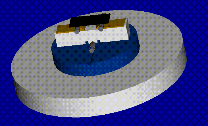
 The alignment issue regarding the base plate has been solved. Two holes
will be drilled into the v-notch plate. The depth of the holes is 5mm. A distance that is equal to the width of the lower holder will separate the holes. Two pins will be inserted into the holes. Interference fit will be used between the pin shaft and
each v-notch plate hole. The lower holder will sit on top of the base roller between each pin. This will allow for the lower holder to be centered on top of the base roller. Also, the v-notch on the v-notch plate is to be filled just enough to center th
e base roller onto the v-notch plate. It is key that only a portion of the v-notch is filled. This will enable the user to easily slide the base roller, lower holder, and bottom rockers out when desired. The combination of the pins and the v-notch
filler enables alignment of the base plate yet maintain the degrees of
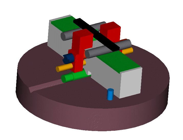
freedom that the people of NIST require. To align the testing specimen, two L-brackets will be used. There have not been any L-brackets found that will meet the requirements necessary for this project. Therefore the L-brackets will be manufactured.
To mount both L-brackets on the test setup, two holes will be drilled
through the lower holder and through each L-bracket. One alignment pin and a binding screw and post will penetrate the outer and inner holes, respectively. The type of pins to be used are Lava Steel Round Pins, which can easily be purchased for $3.56. Th
e
material of the pins is made out of a special bar open hearth steel. Each pin has a tolerance of +0.000" to -0.002". The pins have a tensile strength of 75,000 to 85,000 psi. The Brinell hardness of the material ranges from 165-180. L-brackets will be
used with a double threaded screw so that the rate at which the two L-brackets move toward each other will be equal. Therefore, the specimen will remain in the center of the apparatus and the force will act on the center of the specimen. The brackets co
ntain two pins, a binding screw and post, and two nuts that are welded onto the two L-brackets.
For comments about this page, please contact the author at
claudius@wam.umd.edu

