Design of a Test Bed for High Speed Machining of Ceramic Materials

[Eluminda Orozco] [Steven Birdsall] [Nader Hamouda]
[Jamie Nicholas] [Ian Raun]
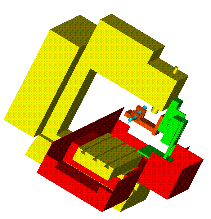
The purpose of this cooperative between the University of Maryland,
College Park and professionals from the dental field is to design a test
bed for the high speed machining of dental ceramics. The ceramic
materials are being tested for response to different operational
conditions. A test bed is in the final stages of design however
improvements are necessary.
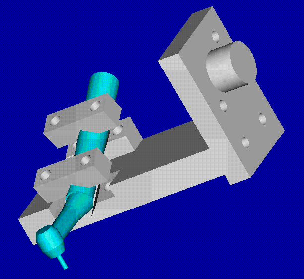
The goal of this project is to improve upon the current test bed for high
speed machining of ceramics. The housing for the dental drills needs to
be improved upon such that different types of drills can be tested using
the same housing. The most important aspect of the housing is that it
ensures that the drill is placed in the housing such that it is
perpendicular to the cutting surface. This surface must be able to firmly
hold the ceramic work piece being tested. In order to ensure that the
testing procedures are properly documented, the rotational speed and the
torque produced by each drill must be measurable. The previous techniques
for doing this proved insatisfactory and need to be improved upon.
One of the objectives of the project was to create a table with the torque at different pressures and angular velocity of the drill. This was needed because different materials are cut better at different torques. A hand held torque measuring device was purchased and used to collect that data.
To create accurate torque vs pressure table the process of collecting the data had to be repeated to get accurate results. Originally the pressure was regulated with a foot pedal. Using the foot pedal made it difficult to get the same pressure when the d ata collection process was repeated. The foot pedal was taken apart and screw was placed in it such that the pressure can be regulated by moving the screw.
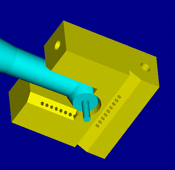
The fluid delivery block was needed to deliver the cutting fluid to the material being tested. The fluid is needed to cool, lubricate, and clean the material while being cut. The block was designed to deliver the fluid at different angles because the ang le makes a difference in the fluid effectiveness.
To recycle the cutting fluid and keep the test area clean a fluid recovery pan was manufactured and installed under the test bed.