
Construction of the map was completed through two separate
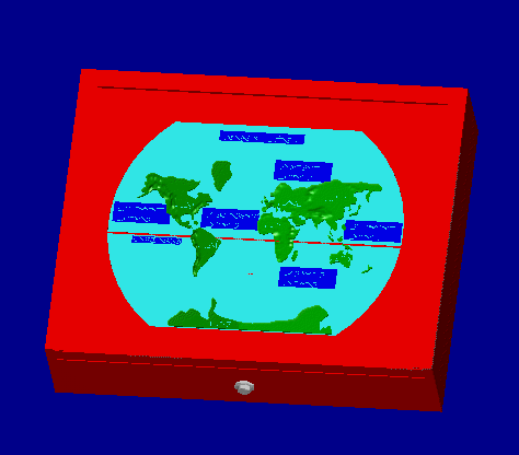
processes. The world map top piece was built using stereolithography
technology. This was necessary to achieve the surface contouring of
the relief map. The lighted display base was created from half-inch
plexiglass cut to size and milled using a CNC milling machine.
The'continent lighting' feature is incorporated mainly as a tool to
encourage interaction in the classroom between sighted and blind
students. The design for this part of the project consists of a
seven-LED circuit powered by a DC source. The LED's are positioned to
individually highlight each continent on the map.
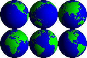
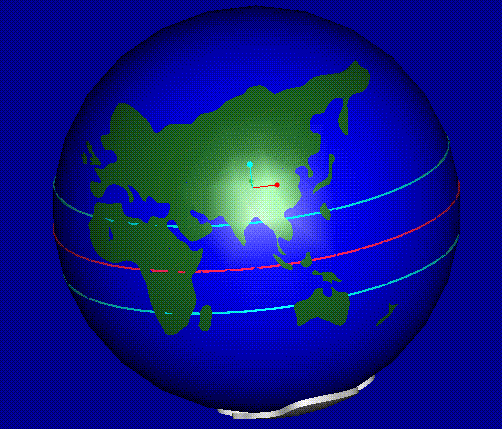
Since a 3D globe had been previously manufactured, our task was
to modify the existing model. All of the conponents were drawn using
Pro/ENGINEER software. First, all the surface manipulations previously
on the globe were removed for North America, South America, Asia, Europe
and Africa. This was done to resolve regeneration conflicts in
Pro/ENGINEER. Next, the actual splines of the continent shapes were
modified to be more geographically accurate. Also, the size of the globe
was enlargered to better show the spacing between the continents.
Once the continent splines were shaped correctly, the surface
cuts of these continents were redone. Next, a hollow sphere was
created for the continents to be mounted on. Using the Assembly
feature on Pro/ENGINEER, all of the continents were placed on the
sphere. Three rings were then added to the globe, each representing the
Equator, Tropic of Cancer, and Tropic of Capricorn. Finally, Pro/ENGINEER
surface manipulation techniques were used to re-apply mountains to the
continents that they were previously removed from.
Because of the complexity to create three dimensional braille labels on a
curved surface in Pro/ENGINEER, the braille labels were not drawn onto the
globe. To
compensate for this, braille labels were manufactured as separate
blocks with braille on them. These blocks were then used as the mold to
create thermoform braille labels. Once created, these labels were attached
to the globe using an adhesive.
All drawing modifications were made using Pro/Engineer software.
A 3D-SYSTEMS SLA-250/40 Stereolithography machine was used for the
construction of both the 2D relief map and 3D globe. The base of the 2D
relief map was constructed using Plexiglas and a Matsuura MC-510V
CNC machine.
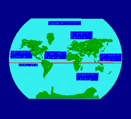
There are two designs for our project. The 2D map was
designed by taking advantage of Pro/ENGINEER's surface manipulation
capabilities. The 'tweak' and 'free form' commands were employed in the
creation of the raised relief features of the map. The braille was
created by first creating a master braille cell, composed of extruded
cylinders rounded at the top. This master cell was then repeatedly copied
and modified to create all the labeling required. The final design was
acheived by assembling all the separate components together (continents,
braille, equator).
2-D Relief Map
National Federation For The Blind
American Federation For The Blind
American Council For The Blind