Team 5
Progress Report
(April 7, '97)

Introduction
Since Team five's last progress report, the group has
been to the Smithsonian on five occasions. Fortunately, two graduate students
(Yi Chien and Li Xun) are working in this area and have offered their assistance.
Initially, a tutorial guide was given to each member of the group and was
subsequently reviewed prior to the first scan. The team is currently in
the process of editing a 3D-digitized scan file using the program Datasculpt.
The following paragraphs will briefly discuss the methodology used in understanding
the 3D-Digitizer (Laser Design Model #3000, see Figure 1 "Huxley"),
scanning editor (Datasculpt), and future goals.
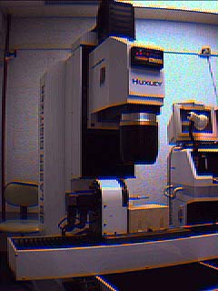 Fig. 1 Laser Design Model #3000, "Huxley"
Application of the 3D-Digitizer
(Laser Design Model #3000)
Digitization is the inverse of
computer aided manufacturing (CAM) and allows the creation of a computerized
representation. In this case, the specimen used was a lag bolt. The laser
scanner operates on the same basis as the computer numerical control (CNC)
machine. For example, the bed of the scanner moves the specimen, in the
X-Y-Z directions, in the same fashion as the CNC machine. In addition,
the laser scanner also includes a rotational feature (A-axis).
Initially, the team did an introductory
scan for a learning experience. During the scan, the group learned how
to set up the initial parameters on the computer that operates the laser
scanner. These parameters define the limits of the Òlag boltÓ
scan. These limits produce a Òscanning windowÓ on the computer,
which enables the operator to view the scanning process. The two types
of scanning processes are ÒrotationalÓ and Òflat.Ó
The rotational scan allows the operator to scan the specimen in the X-Z-A
directions. The X-Y-Z directions are used for the flat scan. For project
five, the group performed a rotational scan (see Figure 2 Front) for the
length of the lag bolt and a flat scan on the cap.
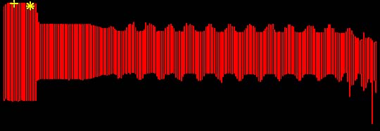 Fig 2. Front View of Scanned Image
Scanning Editor
(Datasculpt)
Datasculpt is the tool used for
the process of editing a scanned file (.SCN). The program allows the editor
to view the scanned object in all of the orthogonal and isometric views.
One of the previously mentioned limits of the scanning process includes
Òline density.Ó This limit defines the distance between each
line scanned on the object. Once in Datasculpt, each line is known as a
clip, which must be edited individually (see Figure 3Clip). Upon completion
of the editing process, Datasculpt is then used for meshing the clips together
to create a 3D surface model.
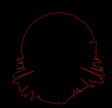 Fig. 3 A single clip of the scanned data (in area of the threads)
Unfortunately, the scanning process
is not error proof. For example, object placement, surface texture, the
laser beam traversing beyond the boundary of the object, and the luster
of the object, all contribute to errors. Therefore, the focus of Datasculpt
is to mitigate, or alleviate the errors, and then manipulate the scanned
lines into a 3D surface model, for which a CAD/CAM system will recognize.
Figure 4 shows a partially edited lag bolt, from the cap up to the yellow
star. It took six hours to scan the length of the lag bolt and eight hours
to edit this small section.
Fig. 3 A single clip of the scanned data (in area of the threads)
Unfortunately, the scanning process
is not error proof. For example, object placement, surface texture, the
laser beam traversing beyond the boundary of the object, and the luster
of the object, all contribute to errors. Therefore, the focus of Datasculpt
is to mitigate, or alleviate the errors, and then manipulate the scanned
lines into a 3D surface model, for which a CAD/CAM system will recognize.
Figure 4 shows a partially edited lag bolt, from the cap up to the yellow
star. It took six hours to scan the length of the lag bolt and eight hours
to edit this small section.
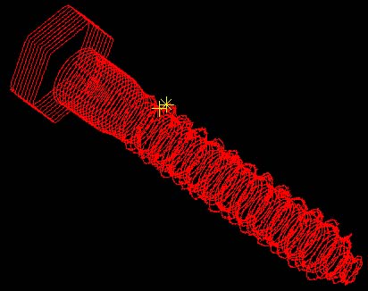 Fig. 4 Isometric view of scanned data
Future Goals of the Team
In the remaining weeks of class,
the group still has three goals to accomplish. First and foremost, the
editing/meshing process for the scanned lag bolt has to be completed. The
work completed thus far, on the digitizer and Datasculpt, has been done
under the advise and guidance of Yi Chien. Yi Chien, having written a thesis
paper on 3D-Digitization, has proven to be a valuable resource to the group.
Secondly, integration of the meshed
file into ProEngineer will probably be the most difficult to achieve, because
of the size of the data files and current drawing programs are unable to
handle these large files. Currently data is able to be transformed into
an STL file for stereolithography, enabling a three dimensional prototype
to be created. Goals involve utilizing Pro/Engineer software to accomplish
this task. An interface routine needs to be created in order to convert
the data from the digitizer output format to that of Pro/Engineer (.IBL)
files.
Finally, creation of the 3D Prototype,
using the transformed data from the lag bolt scanning, will complete the
project. Whether this will be done using either the CNC or STL machine
is uncertain at this time.
Back to Project 5 Homepage