
ENME 414 TEAM 2

In the this project, our team will use the advanced features of Pro/Engineer to create a 3-D topographical map and globe that will be rapid-prototyped on a stereolithography machine. The map and the globe will fit the educational needs of the Maryland School for the Blind in Baltimore, Maryland.
The Needs of Our Customers
The purpose of this project is to create a topographic map and globe to teach blind people about the elevations of the United States and the Earth. To research the school's needs three members of our group visited the Maryland School for the Blind. Initially our group thought it would be easy to create the map-just trace a map and layer the various elevations, but faculty at the school informed us that the change in height would be to subtle for the blind people to notice. Therefore, we need to use small symbols that create a texture to represent a change in elevation.
If the boundaries of the continents are very detailed the blind people will experience a form of sensory overload. To prevent this the shapes of the continents will be simplified.
The map and the globe must be in color or labeled in some way
that the teachers who are not blind may also distinguish the various
continents.
The Map of the US
First we traced a rough out line from a typical mercator map of the US on to a transparency. Next we taped the transparency to the computer monitor. Then we traced the transparency on a datum plane in Protrusion using Splines . Since the maps were already to scale we used whatever dimension was the Pro/ENGINEER default. Then we used the Quilt and Tweak features to pull out the mountains. We used Cut to put in the Mississippi River. The line at the north pole is to show the blind where north is.
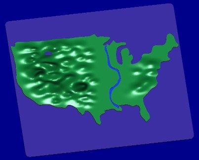
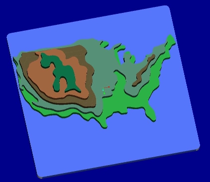
Then we created a color map to show the various elevations of the US and to act as an assembly drawing for the painting of the final product.
The team will add brail to label our drawing for
the blind using the Copy feature to replicate sets of six
flat conical "dots"-to make the needed letters we will
remove the unneeded "dots."
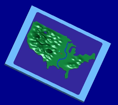
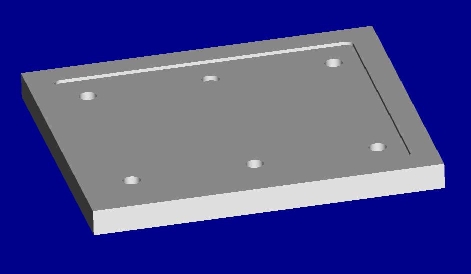
It Is very common in thin models produced on the SLA machine. We have designed a base plate on Pro/ENGINEER to hold the SLA model reducing deformation. A color Assembly drawing on Pro/E shows that the two models will fit together very well . Our team has converted the model for the base plate into NC Code using Pro/ENGINEER. Once the code is satisfactory, we will machine it on the Matsurra Vertical CNC milling machine from Plexiglas. We have already generated the *.STL file for the US map and produced the prototype. Using The SLA machine and the CNC mill together practically eliminates the problem of tolerancing when using bolts.
An assembly model of the base plate and US map looks like:
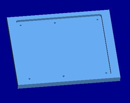
We used Pro/MANUFACTURE annd Pro/NCCHECK to set up a tool path to manufacture the pocket on the base plate. Here is the resulting pocket:
The next step was to generate the NC code to drill and bore the holes. Shown below is the workpiece on Pro/ENGINEER after both the pocketing and boring procedures
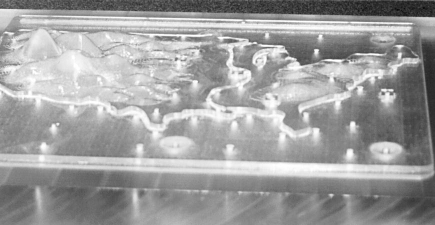
Finally we assembled the SLA part and the base plate Below are two photographs of the actual assembly.
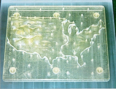
This black and white photo shows the mountains very well.
The Globe of the Earth
We created the two main parts of the globe by
projecting a cut on a hemisphere. We did the Americas
on one hemisphere, and europe and asia on another.
We also made parts for Austrailia and Antarctica. Finally
we assembled all the parts to complete the globe. Below
are two pictures of the assembled model. The line (circle)
at the north pole is to show the blind where north is.

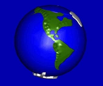
Currently the Globe is being created on the SLA machine It will take three days to produce as the model will consist of over 18,000 layers. A picture will be posted as soon as the model is complete.