Chemistry 498A/C Laboratory
Name___________________________________

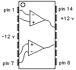
2. Voltage follower. Using the upper of the two op amps in this package, wire up a voltage follower by connecting the output (pin 12) to the inverting input (pin 1). Switch on the power to the breadboard. Connect the output (right-hand set of terminals) of a Heath Voltage Reference Source (VRS) to the non-inverting input (pin 2). Connect the ground of the VRS to the breadboard ground. Set the VRS to 5.00 volts. Now read the output voltage of the voltage follower (pin 12) with a digital voltmeter. It should be very close to 5.00 volts.
Now connect a (roughly) 2K resistor between input of the voltage follower (pin 2) and ground and notice the drop in voltage read by the digital voltmeter when the resistor is connected. Then remove the resistor and connect it between output of the voltage follower (pin 12) and ground. Notice the change in voltage read by the digital voltmeter when that resistor is connected. Interpret these results in terms of loading error and the output resistance of the VRS and of the voltage follower.
3. Inverting amplifier. Wire up an inverting amplifier with a gain of 1000 by connecting a 4.7 M (yellow-violet-green) resistor between the output (pin 12) and the inverting input (pin 1) and a 4.7K resistor (yellow-violet-red) between the inverting input (pin 1) and a free point on the breadboard (which will be the input to the inverting amplifier). Ground the non-inverting input (pin 2). Switch on the power to the breadboard. Connect the output of the voltage reference source (VRS) to the amplifier input (free end of the 4.7K input resistor). Connect the ground of the (VRS) to the breadboard ground. Set the output range to mV. Observe the output of the amplifier (pin 12) with the multimeter.
b. Disconnect the VRS and ground the input of the amplifier by connecting pin 2 to ground. Now use the multimeter to measure the output voltage and calculate the input offset voltage (divide output offset by the gain).
c. Observe the output of the amplifier (pin 12) with the oscilloscope. Switch the oscilloscope's input switch to AC and turn up the vertical sensitivity so you can see the output noise from the amplifier. Calculate the effective input noise.
(b) Disconnect the input and leave it open. Measure the output voltage and calculate the bias current. Compare to the value you measured in the previous experiment.
(c) Assuming that the differential input resistance of the op amp is 1 MOhm and that its open loop gain is 105, calculate the fraction of the input current that flows into the op amp rather than through the feedback resistor. It should be very small, even though the differential input resistance is small compared to the feedback resistance. Explain.
RETURN to the CHEM 498C Home Page