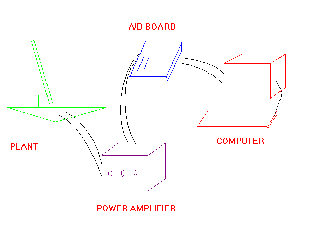

In general , the system is controlled via an IBM compatible computer. The main components of the system are as shown in the above figure. A computer equipped with data acquisition and control board(DACB) performs the control. The DACB measures signals from sensors on the plant and converts them to digital signals which can be acquired and processed by the computer. A control program residing in the computer performs the operarions required on these signals and computes output voltages that are written to the DACB. The DACB outputs are connected to Amplifiers which in turn drive the actuator in the system.
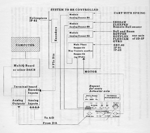
Now let me give you a figure which will enable you to understand the various transactions that take place within the system.

As you know the computer takes in and gives out only digital signals, an analogto digital converter(A/D) and vice-versa(D/A) is required. The data acquisitionand control board used in the system is the MultiQ board. This is a general purpose data acquisition and control board which has 8 single ended analog inputs,8 analog outputs, 8 bits of digital input,8 bits of digital output,3 programmable timers and 6 encoder inputs. All wiring to the board is performed through the terminal board which is supplied with the board.
A Power Amplifier is provided in the system to magnify the voltages generated by the computer. This is essential because computer gives out only small voltages of the order of 5 volts where as high voltages are required at the plant. The Power Amplifier drives the actuator. Each power module has several connectors referred to as the "quick connect system". The input to the power amplifier is the output of one of the D/A channels on the board. For MIMO(multiple input multipleoutput) systems you will need as many power amplifiers as there are actuators. But since our system is a SIMO(single input multiple output) one power amplifier is enough for us. In our system the voltage signal from the computer which gets transformed into the force on the cart is the only input. Whereas we can have multiple outputs like the cart position, the angle of the inverted pendulum, the angle of the see-saw, or the position of the second cart connected to the first (we can have the second cart also).
The DACB board can be equipped with up to 6 encoder decoders. Encoder measurements are fed directly to the terminal board.

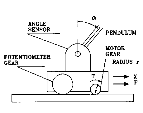
The first step in any control system design is to model your system. The basic plant you'll be working with is a simple cart riding on a track. The track is assumed to be frictionless, and the cart is actuated by a voltage-controlled rotary motor which drives the cart's wheels through a gear system.
The differential equation of the frictionless cart of mass m is simply,
The system is driven by a DC motor with the following dynamics:
where I is the current through the motor, r is the radius of the gear connecting the motor to the track, K is a combined motor torque constant, and R is the resistive load of the motor. Solving this equation for I results in:
The torque produced by the motor is proportional to the current I,
Combining these relations, the applied force on the cart due to the motor is,
Substituting in the known system parameters m, R, r, and K results in the final transfer function,

   R(s) =  Reference signal (sinusoidal signal)
   C(s) =  Cart position
   Gc   =  computer control system
   K    =  Power amplifier
   G1(s)=  motor trannsfer function
   G2(s)=  cart dynamics
   H1(s)=  Encoder
The system can be realised as in the above block diagram. But the components to the left of the dash-line i.e, R(s) and Gc are not tangible because they are in the computer.