
PID Design for a DC Motor
NOTE: This tutorial is a modified version of an online control system tutorial provided by Carnegie Mellon University and the University of Michigan.
As you should recall from Studio #5, the transfer function between shaft speed
and input voltage for a DC motor is given by:

Let's again consider a unity-gain negative feedback control loop with a controller added to the forward path:
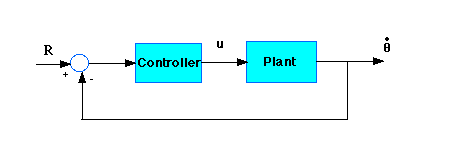
We previously considered a proportional controller to modify dynamic and steady-state behavior of the system. Now let's design a PID controller and add it into the system. First create a new m-file and type in the following commands(refer to main problem for the details of getting those commands).
    J=3.2284E-6;
    b=3.5077E-6;
    K=0.0274;
    R=4;
    L=2.75E-6;
    num=K;
    den=[(J*L) ((J*R)+(L*b)) ((b*R)+K^2) 0];
Recall that the transfer function for a PID controller can be written in either of the following forms:

Let's first try using a proportional controller with a gain of 1.7. Add the following code to the end of your m-file:
    Kp=1.7;
    numcf=[Kp];
    dencf=[1];
    numf=conv(numcf,num);
    denf=conv(dencf,den);
To determine the closed-loop transfer function, we use the cloop() command. Add the following line to your m-file:
[numc,denc]=cloop(numf,denf);
Note that numc and denc are the numerator and the
denominator of the overall closed-loop transfer function.
Now let's see how the step response looks. Add the following to the end of your m-file, and run it in the command window:
    t=0:0.001:0.2;
    step(numc,denc,t)
You should get the following plot:

Now lets take a look at the step disturbance response. Add the following to the end of your m-file, and run it in the command window:
    numdcl=conv(numc,1);
    dendcl=conv(denc,Kp);
    step(numdcl,dendcl,t);
You should get the following plot:
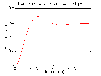
From the plots above we see that although the steady-state error looks good the settling time is too large, as is the overshoot. We also see that the steady-state error to a disturbance is large. Recall from PID tutorial that adding an integral term will eliminate the steady-state error and a derivative term will reduce the overshoot. Let's first try a PI controller to get rid of the disturbance steady state error. Change your m-file so it looks like:
    J=3.2284E-6;
    b=3.5077E-6;
    K=0.0274;
    R=4;
    L=2.75E-6;
    num=K;
    den=[(J*L) ((J*R)+(L*b)) ((b*R)+K^2) 0];

    Kp=1.7;
    Ki=20;
    numcf=[Kp Ki];
    dencf=[1 0];
    numf=conv(numcf,num);
    denf=conv(dencf,den);
    [numc,denc]=cloop(numf,denf,-1);
    t=0:0.001:0.4;
    step(numc,denc,t)
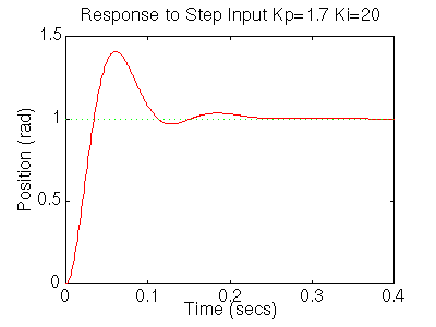
You should get the following step response:
Lets see what happened to the step disturbance response, add the following to your m-file:
    figure
    numdcl=conv(numc,dencf);
    dendcl=conv(denc,numcf);
    step(numdcl,dendcl,t);
You should get the following plot:
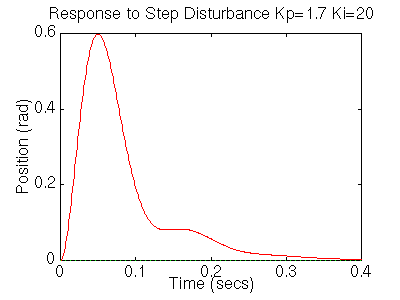
The settling time is still too long. Let's increase the gains in order to speed up the response. Go back to your m-file and change Ki to 200 and Kp to 17. Rerun the file and you should get plots like these:
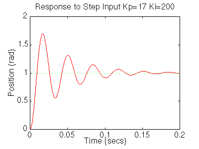
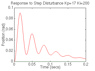
Now we see that the response is faster than before, but the large Ki has worsened the transient response (big overshoot). Let's now try a PID controller to reduce the overshoot. Go back to the m-file and make the following changes to look at the step response.
    Kp=17;
    Ki=200;
    Kd=0.15;
    numcf=[Kd Kp Ki];
    dencf=[1 0];
    numf=conv(numcf,num);
    denf=conv(dencf,den);
    [numc,denc]=cloop(numf,denf,-1);
    t=0:0.001:0.1;
    step(numc,denc,t)
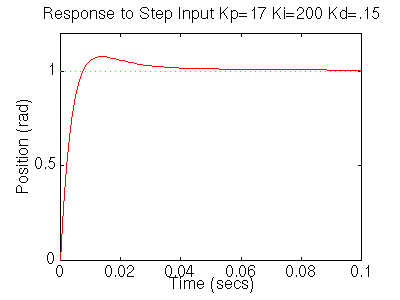
Rerun it and you should get this plot:
Your step disturbance plot should look like this:
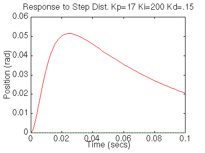
We now see that our step response looks really good, it has less than 16% overshoot and the settling time is roughly 40ms, and there is no steady-state error. However the step disturbance response is now really slow. Lets increase Ki to speed up the disturbance response. Change Ki to 600 in your m-file and rerun the file. You should get the following plots:

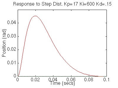
We now can see that the step response has a settling time of roughly 40ms,
it has less than 16% overshoot, and it has no steady state error. The step disturbance
response also has no steady state error. So now we know that if we use a PID
controller with
Kp = 17,
Ki = 600,
Kd = 0.15,
all of our design requirements will be satisfied.