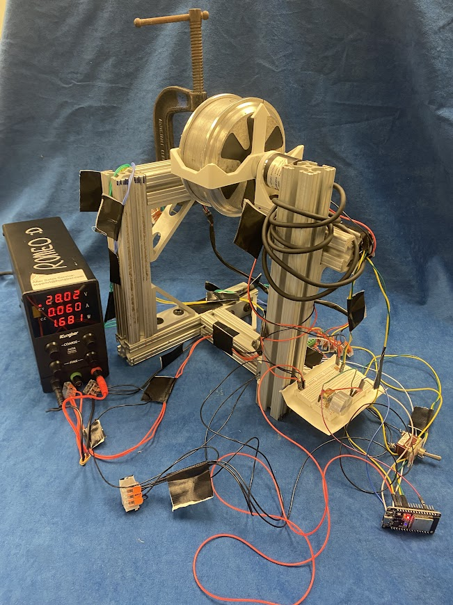
For my final project submission, I used a PD controller and an ESP32 to control a brushless DC motor. This README contains the hardware used by the system, the system electronics and wiring, and the software to drive the system. By the end of this README, you should build and replicate the results exaclty from this final project! At least, that is my hope with this README :)
In your project configuration, specifically in sdkconfig, you must change the following parameters:
Change this too:

```CONFIG_FREERTOS_HZ=1000
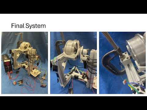
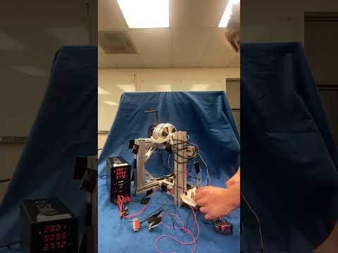
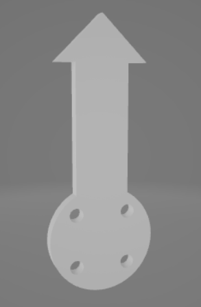
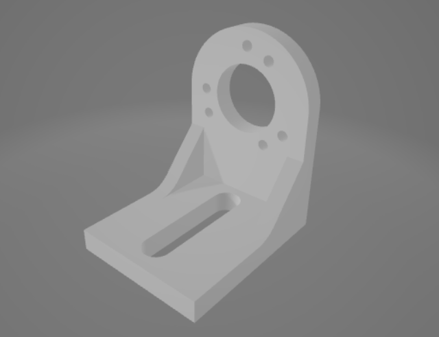
The system relies on three 3D prints to connect the motor and the encoder. The motor doesn't have any traditional mounting holes since it was original designed to spin a tire really fast, and the tire was built into the rotor. As such, we need to print an adapter to allow us to connect the motor and the encoder. We also need to print a mount for the encoder.
The two prints that are attached to the motor are the armature and direction arrow. You can find them here here
Motor-To-Encoder Armatrure:
Direction Indicator Arm:
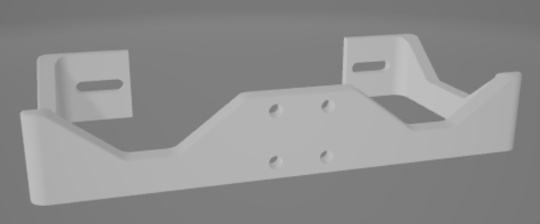
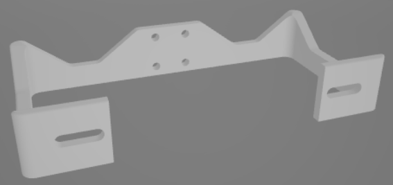
The only print needed for the encoder is it's mount, which you can find here
Encoder Mount:

Because this is a little complex and also not necessarily required (another mounting method can be designed), see the CAD for more detail [TODO - ADD LINK]
[TODO - ADD PICTURES OF THE CAD]
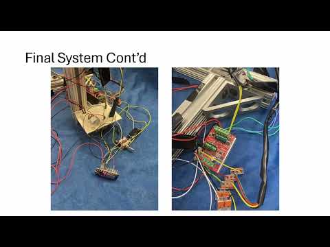
Below is an electrical schematic of the system. You can utilize the WAGO connectors for most connections, however you will need jumper wires for connecting to the ESP32 and other peripherals. The general implementation is up to interpretation, however the exact wiring of the system used for this project is reflected in the wiring diagram!
[TODO -ADD PICTURE OF WIRING DIAGRAM]
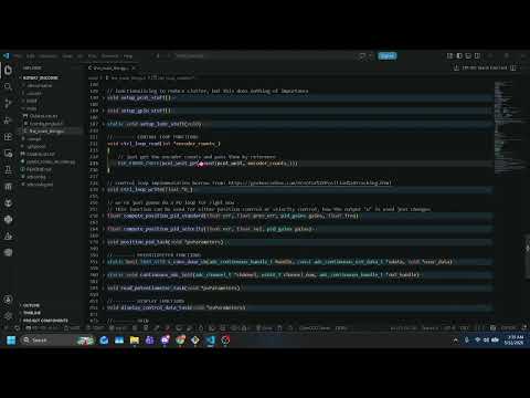
After installing Visual Studio Code, ESP-IDF, and the VSCode ESP-IDF extension, you can then clone this repository, or whatever means you want to get the ESP32 project code onto your own machine. Once it's on your machine and your project is configured, you should be able to build, flash, and monitor the code out-of-the-box! There are no external libraries utilized, just ESP32 libraries, C libraries, and FreeRTOS libraries (which should be downloaded with ESP-IDF).
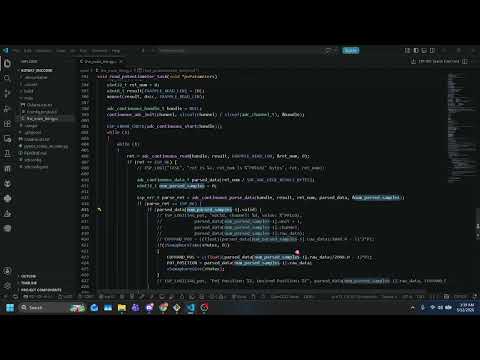
You will find all the code to run this project in one simply file: the_main_thingy.c. This File is located in the FinalProj/rotary_encoder/main/ folder. It's CMakeList.txt file (generated by ESP-IDF) is also in that file
There are three main tasks being run by the ESP32:
The control task, running at 1000 Hz on CORE 1
The potentiometer task, running at 100 Hz on CORE 0
position_pid_task()]This task runs the PD control loop, and thats it! It reads the encoder counts from the onboard pulse counter, computes the command signal, and then writes a PWM value. The control loop itself is very standard:
ctrl_loop_read(int *encoder_counts)]pcnt_unit_get_count()compute_position_pid_standard(float err, float prev_err, pid_gains gains, float freq)]ctrl_loop_write(float *U)]ledc_set_duty() and ledc_update_duty()There is an additional update function called compute_position_pid_velocity(float err, float vel, pid_gains gains) which uses the velocity as a damping factor, rather than the change in error
There are two custom data structure implemented to ease function inputs, the pid_gains struct and the pid_mode enumerator. pid_gains stores the PID gains for the controller. The members of the struct Kp, Kd, and Ki are set before the beginning of the while loop in the task. pid_mode is used to switch between change in error PID or direct velocity PID
To reduce the need to divide, many conversion factors which would require divison are pre-computed before the beginning of the while loop. In addition, rather than deriving the position measurements to get measured velocity using the common formula:
(p(t) - p(t-1))/dt
We use:
(p(t) - p(t-1))*freq
Since our control frequency is stable (or at least, should be thanks to FreeRTOS), we can say that our delta time is "constant" and 1/dt = 1/period = frequency. Thus, saving us the need to divide in order to get velocity. This is done a lot, where the inverse is computed ahead of time and then multiplied by, in an attempt to not have to divide.
We also used vTaskDelayUntil() rather than vTaskDelay() since we want our code to mandate a 1kHz frequency. Seemingly, the control loop computation is faster than 1 ms, allowing us to wait until we 1ms has passed before returning
Finally, we also store the the actual position, desired position (or commanded), the encoder counts, the error, and the control signal in global buffers labeled ACTUAL_POS, ENCODER_COUNTS, ERROR, CONTROL_SIGNAL so that our display task can handle printing to the terminal, rather than the control loop.
We SHOULD filter the velocity signal using a low-pass filter (example from here: https://kiritchatterjee.wordpress.com/2014/11/10/a-simple-digital-low-pass-filter-in-c/) because it's WAY noisy! But I haven't implemented that yet. I should probably filter the potentiometer too!
read_potentiometer_task()]This is pretty much stripped directly from their example, as there was no point in fixing a broken clock if it's right twice a day, or something like that! You can find the ESP32 source code here: https://github.com/espressif/esp-idf/tree/v6.0.1/examples/peripherals/adc/continuous_read
display_control_data_task()]This task is very straight forward. Get the data from the buffers, and then print it to the console!
Its important to note that the PWM generator is generating a signal with a frequency of 20kHz. From online research (googling), 20kHz seemed to be a good PWM frequency to ensure good motor control. With this goal in mind, we needed to calculate the control duty resolution (see PWM generator below), and found that our maximum PWM command was 2047 bits, and our resolution was 1 bit, so we have 2047 different possible commands to send to the hardware.
Many of the things implemented for this project were borrowed from other pioneers on the internet. Here are my sources:
Without the above documentation, this project (which I started on 5/8, and ended on 5/11... my parts didn't come in until 5/6!!) I would have NEVER been able to actually build this system, let alone get it running. But, I've gotten it running, and I'm quite proud of the little scamp. The poorly tuned, aggressive, spaghetti-like scamp. Hopefully if you are reading this, you may also one day be proud of your own little PID testbed, maybe even this very one!