MANN GCA DSW 4800 Wafer Stepper
SPEC - EDIT COMMAND DIALOGS
SPEC and EDIT are closely related and most of the prompts for these commands
are identical.
Keyboard Editing Controls
For all CTRL functions, the CTRL key is held down while the desired
letter key is pressed.
-
?
-
The "?" key backs up one line of questioning in SPEC and EDIT modes.
-
D
-
The "D" key, in SPEC and EDIT modes, when typed at the first PLUG or DROPOUT
parameter input line, will display a graphical representation of previously
specified plug location(s).
-
CTRL-Q
-
Aborts editing.
-
CTRL-U
-
Erases the current line of input and positions the cursor at the beginning
of the deletion.
-
BACKSPACE / DELETE
-
Removes the last character typed.
FILE AND SYSTEM PARAMETERS
-
OUTPUT JOB NAME:
-
The filename for the job. Can be up to two strings of up to 6 characters
each.
-
METRIC OR ENGLISH UNITS:
-
Parameter units of measure for the file. Use metric.
-
COMMENT:
-
Text information explanatory of the job file entered by the operator. Can
be up to 80 characters.
-
TOLERANCE:
-
The allowable laser stage positioning sensitivity necessary for the shutter
to open. One is the least tolerant, six is the most tolerant. Three gives
the best overall performance.
-
SCALE CORRECTIONS:
-
Adjusts step size to allow for wafer dimensional changes across levels
or mislocated reticle fiducials. Similar to the wafer scale button box
control, but without the interactivity. Not normally used at LPS.
-
ORTHOGONALITY:
-
Adjusts the angle between the rows and columns of an exposure matrix. Not
normally used at LPS.
-
WAFER DIAMETER:
-
Normally the size of the wafer chuck, which at LPS is 76 mm (3 inch). The
software places an autofocus boundry of 3 mm around the circumference of
the wafer, thusly reducing the imageable wafer diameter to 70 mm.
ARRAY PARAMETERS
-
STEP SIZE:
-
The distance between centers of successive exposures.
-
COUNT, SPAN OR ALL:
-
COUNT invokes a sub-prompt for specifying the number of steps in rows or
columns.
SPAN invokes a sub-prompt for specifying a physical X or Y distance
in which to limit exposures.
ALL will cover all of the usable X or Y dimension with exposures.
-
TRANSLATE ORIGIN:
-
Shifts the entire exposure matrix in X and/or Y. A parameter of zero centers
the array to the wafer center.
-
DISPLAY?:
-
Produces a graphic display of the exposure array steps on the wafer.
-
Layout?:
-
Produces tabular information regarding the size and centering of the exposure
array.
-
ADJUST?
-
Initiates sub-prompts for adding or subtracting rows and columns from the
array.
-
ROWS-COLUMNS : MORE/SAME/LESS:
-
Each MORE response increases the row or column count by one. SAME does
not alter the row or column count. Each LESS response reduces the row or
column count by one.
ALIGNMENT PARAMETERS
-
STANDARD KEYS:
-
For specifying alignment dice. If "yes", the software chooses the alignment
dice. If "no", the operator must specify the row and column positions for
the right and left alignment dice.
-
KEY OFFSET:
-
The X-Y distance from the die center to its alignment mark (cross or fiducial).
-
ALIGNMENT DIE CENTER:
-
For non-standard alignment dice, operator specifies the row and column
position of the right and left alignment dice.
-
EPI SHIFT:
-
For level exposed after EPI deposition. EPI layer will appear shifted with
respect to previous level exposure. This parameter range is 5 microns.
Not normally used at LPS.
PASS PARAMETERS
-
NAME:
-
The name for the pass. Can be up to two strings of up to 6 characters each.
-
COMMENT:
-
Text information explanatory of the pass entered by the operator. Can be
up to 80 characters.
-
EXPOSURE:
-
An exposure time between 0.050 and 128.000 seconds, incremental by 0.001
seconds. Exposures greater than four seconds are executed as multiple exposures
of four seconds each.
-
FOCUS SETTING:
-
The focus for the exposures. The calibrated benchmark is 251 where 1 =
0.25 micron.
-
SHIFT:
-
Shifts the entire exposure matrix in X and/or Y. This value is added to
any TRANSLATE ORIGIN value.
-
ARRAY, PLUG OR LABEL:
-
ARRAY exposes all array dice except DROPOUTS.
PLUG exposes only specified array dice locations.
LABEL is not supported on the LPS hardware.
-
DROPOUTS:
-
Specifies row/column array dice locations not exposed during an ARRAY exposure.
Type D or V at any ROW prompt to overview all dropout locations.
-
PLUGS:
-
Specifies row/column and offsets of array dice locations to be exposed
during a PLUG pass. Type D or V at any ROW prompt to overview all plug
locations.
-
OUTPUT DEVICE SPECIFICATION:
-
The filename for the job. Can be up to two strings of up to 6 characters
each.
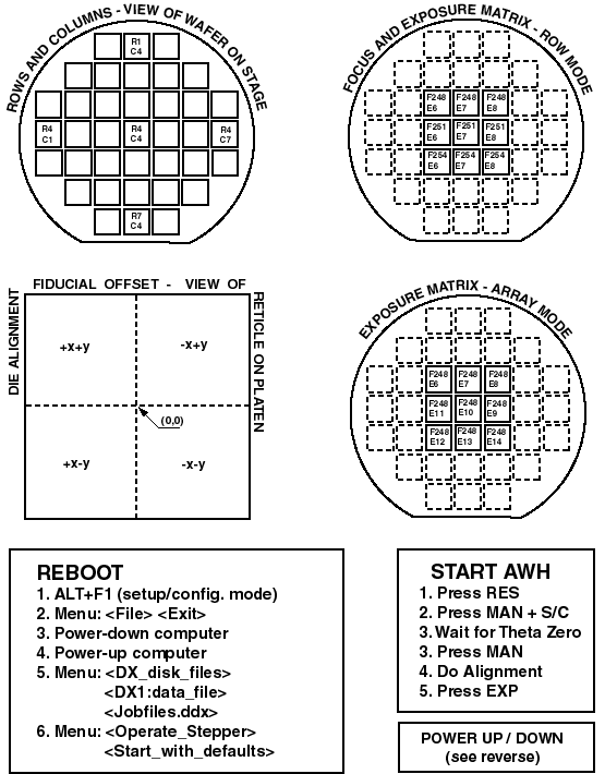
DICE LOCATION CONVENTIONS
Operator's point-of-view of wafer on stage.
ROWS               COLUMNS

     1    2    3    4    5    6    7    8
1   R1C1                               R1C8
2
3
4
5                       R5C5
6
7
8   R8C1                               R8/C8
OFFSET CONVENTIONS (mm)
Operator's point-of-view of reticle on platen.
            +y

      +x+y      -x+y

      +x     0     -x

      +x-y      -x-y

            -y
WHOLE WAFER ALIGNMENT
Whole wafer alignment allows for both the left and right side wafer
alignment marks to be simultaneously visible on the split-screen monitor.
To do so:
-
Specify "standard keys".
-
Step size must be greater than die size.
-
Specify step size to be the wafer alignment microscope objective spacing
(63.5 mm) divided by the number of array columns less one (columns
- 1) : 63.5 / (n - 1).

