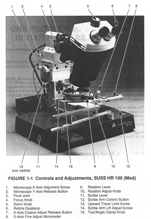
Karl Suss HR-100 Scriber
Scribing Procedure
- Position the scribe location:
- For the first scribe with the microscope reticle crosshair.
- For subsequent scribes with the wafer stage x-axis micrometer.
- Position the wafer so that the scribe tool tip, when lowered, will be just off of and in front of (towards the operator) the wafer.
- Depress and hold down the scribe arm control button to lower the scribe arm.
- Move the scribe lever towards the operator, bringing the scribe tool tip up and over the edge of the wafer.
- Continue the scribe lever movement for the desired scribe length.
- Release the scribe arm control button to raise the scribe arm.
Full Procedure
- Wafer piece should have a good straight crystal-plane edge from which to scribe. Thinned pieces, especially those thinned by the CMP procedure described elsewhere in this manual, may have rounded/tapered edges which do not scribe or cleave well. It may be necessary to first scribe and cleave an edge from which to perform the scribing operations for the devices on the wafer piece.
- Mount sample piece on cleaving tape of sufficient size to cover at least the central-most wafer chuck vacuum ring.
- Lamp illuminator power supply switch ON.
- Scribe lever fully to front of machine.
- Center and roughly X-Y align sample piece on wafer chuck.
- Adjust on/off the wafer chuck vacuum ring control screws for the size of the cleaving tape.
- Wafer chuck vacuum switch ON.
- Adjust scribe arm force adjust screw. For thinned (~100 µm) III-V substrates the screw should be located approximately one inch forward from it's rearmost (least force) position.
- With scribe arm in lowered position, adjust scribe arm depth adjust screw to locate scribe tool tip at approximately one-half of the substrate thickness. DO NOT ALLOW SCRIBE TIP TO CONTACT THE WAFER CHUCK.
- Align sample:
- Make a reference scribe on the full y-axis dimension of the sample (at an extreme x-axis sample location).
- Use the scribe lever to scan the scribe. Adjust X-Y-Theta until scanning produces parallelism between the reference scribe and the microscope reticle cross-hair. Higher microscope magnifications produce finer alignments.
- Sample is now aligned to the wafer stage movement.
- Proceed with making the cleaving scribes. Generally, the scribe length should be approximately the lesser of 3 times the x-axis length between scribes or 2 millimeters. Position the scribe location with the Y-axis stage movement micrometer, which is calibrated to 0.5 µm per revolution.
- After scribing is complete, switch OFF the wafer chuck vacuum and microscope illuminator power supply.

Not Shown in Figure:
- Scribe Arm Depth Adjust Screw
- Located at the center-rear of the machine, roughly in-line with the scribe arm.
- Scribe Arm Movement Speed Adjustment Screws
- Located at the center-rear of the machine.
- Scribe Arm Force Adjustment Screw
- Located on the right-side if the scribe arm.
- Wafer Chuck Vacuum Switch
- Located at the right-rear of the machine.
- Wafer Chuck Vacuum Ring Control Screws
- Located on the side of the wafer chuck.
- Microscope Illuminator Power Switch
- Located on the illuminator power supply separate from the scriber.
